|
bottom of the modulator panel. Its input comes from the station control-room amplifier which in
turn, is fed by the studio control amplifier at the Travelers' Grove Street building in Hartford.
The speech amplifier and modulator system is, to say the least, effective. A "20-db.-down"
(0.01-milliwatt) speech amplifier input signal is sufficient to give 100% modulation of the 50-kw.
transmitter output.
THE 5-KW. LINEAR AMPLIFIER
___The modulated output of the UV-849 excites the first linear amplifier which uses two UV-863,
10-kw. water-cooled tubes in push-pull. Plate power for these tubes is furnished by the 350-kw.
20,000- volt three-phase series mercury-vapor rectifier. The output voltage of the rectifier is
dropped to 15,000 for this stage, by resistors. Plate current to both tubes is 1 ampere; total plate
input is 15 kw. Filament power is supplied by direct-current generator; the filament voltage is 22
and the current to each tube is 52 amperes. Negative grid bias of 320 volts is supplied from
the bias generator and is fed to the grids from a center-tap on the grid tank inductance.
___The grid circuit of this stage is inductively coupled to the plate circuit of the modulated
amplifier. The grid coupling coil is connected by a short feed-line to a high-C tank circuit to
which the grid leads are, in turn connected. Across this grid tank and the grids, is connected an
Ohmspun |
|
resistor. The circuit is the same as that shown in the description of the linear amplifier of
the 'phone transmitter in the April, 1929 issue of QST. Grid excitation is controlled by varying the
coupling to the modulated amplifier plate
coil and by regulating the resistance of the Ohmspun unit.
___The plate capacitance of the tubes is neutralized by a pair of high-voltage three-plate variable
condensers "Cross-connected" between grid and plate, plate and grid, of the respective tubes. In
neutralizing the amplifier, a low-reading thermocouple ammeter is connected in the tank circuit and,
with excitation reduced and plate voltage off, the neutralizing condensers are adjusted for minimum
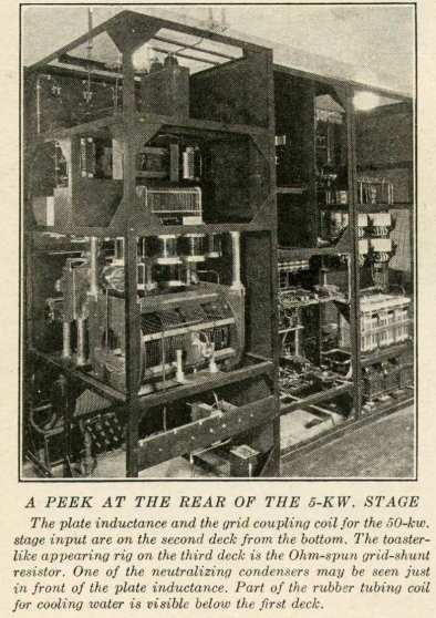
current in the plate tank. The plate inductance is similar in construction to the inductances of the
lower stages. It consists of copper edgewise-wound ribbon on a wood-strip form. High-voltage fixed
condensers connected across this inductance tune it approximately to resonace while fine tuning is
accomplished by means of a rotatable aluminum ring mounted in the plane of the coil turns at the
center of the inductance. This ring is referred to as the "flipper." It is rotated by an insulating
shaft terminating in a knob on the panel front. With this adjustment, tuning over a range of
approximately ten kilocycles is possible. This scheme for fine adjustment is used in all tuned
circuits of the transmitter not equipped with variable condensers. It should have many applications
in amateur transmitters and no doubt an adaptation of the idea would be applicable to receiver
tuning as well. At amateur frequencies, the possible frequency variation would be considerably
greater than at the lower broadcasting frequencies because the change in distributed capacity and
inductance of the coil would be affected in greater proportion. Perhaps the amateur transmitters and
receivers of the future may be visualized as aggregations of fixed condensers and coils tuned by a
variety of aluminum rings or discs. While the idea may not be new, its practicality is given |